Smart Mechanics: Moving Beyond the Vertical Drop
How realigned track geometry and continuous gradients transform gravitational acceleration into continuous H-constant grid inertia.
Inside the GMEG-Zero Machine
A synchronised, closed-loop mechanical asset engineered for continuous kinetic energy recovery and physical grid anchoring.
The Core Machine Mechanics
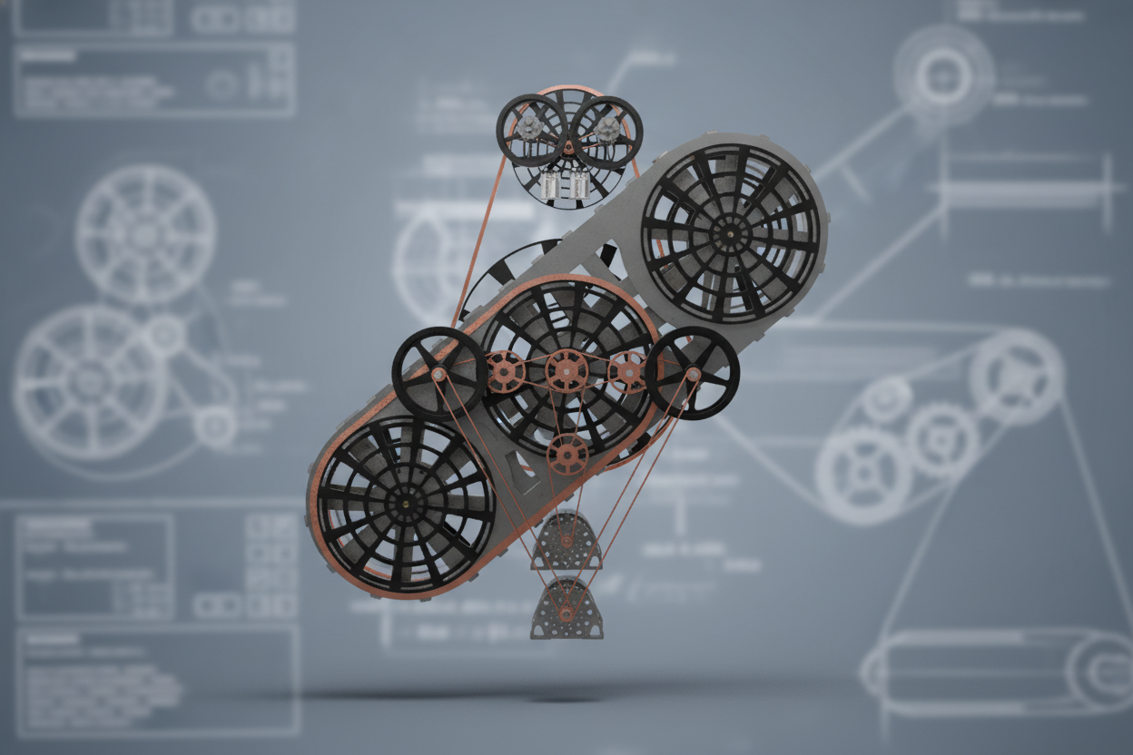
GMEG-Zero isn't a single vertical drop weight or a simple spinning flywheel. It’s a synchronised mechanical machine running an interconnected loop of weights along a sloped track.
By coordinating five integrated control layers, the platform manages weight distribution, track angles (± 30°), and momentum in real time:
- Smooth Power Generation:
Smooths downward weight acceleration into steady rotational torque delivered straight to the drive shaft. - Active Energy Recovery:
Recycles internal braking and supercapacitor energy across corner turns to cut motor power draw by up to ~50% (~40.05% baseline). - Continuous Grid Anchor:
Delivers uninterrupted physical spinning inertia (H-constant) with zero capacity degradation over a 30-year asset life.
Grid Connectivity & Startup Sequence
How GMEG-Zero transitions from idle to closed-loop equilibrium in two track revolutions.
The 3-Step Startup Protocol
01. Buffered Trickle-Charge
Instead of pulling high-peak surge currents from the grid, internal supercapacitors are trickle-charged over a multi-minute window to avoid grid shock.
02. 2-Revolution Kinetic Ramp-Up
Activating the track pitch initiates multi-mass momentum, bringing the GMEG as well as the KETS flywheels up to operating speed over two initial track revolutions, while the primary motors charge their flywheels and DPES buffers. By Revolution 2, the onboard supercapacitors are fully charged and the energy scavenging loops engage - dramatically reducing motor power draw as the system locks into steady-state inertia.
03. Auxiliary Handoff & Steady Export
At the end of Revolution 2, internal energy recovery loops (DPES/KETS) assume full auxiliary loads. The machine achieves kinetic equilibrium and exports net physical torque directly to the grid.
4-Phase Force Extraction Loop
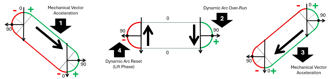
Mapping continuous mass momentum across four discrete track phases during every revolution (Fast-tracked UK IPO Patent Application GB2602284.8).
The 4 Track Phases
Phase 1: Primary Downward Gravity Drive
Masses accelerate along the main 30° sloped track, translating weight directly into primary rotational torque.
Phase 2: Active Track Tilt & Apex Transition
As masses enter the downward turn, the system actively tilts the track (30° → -30°) at a predetermined interval. This realigns the path, prevents gravitational stall, and removes structural shock loads.
Phase 3: Secondary Downward Gravity Drive
Sustained torque transfer along the lower parallel slope (-30°), keeping rotation smooth and momentum completely steady.
Phase 4: Upward Mass Reset & Drag Neutralisation
As trailing weights push down Phase 3, leading weights round the corner turn. The system uses the momentum and kinetic energy of the full mass train to cancel out upward drag and keep net energy positive during the track reset (-30° → 30°).
Subsystem Integration & Hardware Layers
Five synchronised mechanical and control layers engineered to maintain net kinetic equilibrium and grid stability.
The 5 Structural Pillars of GMEG-Zero
01. Primary Drive Core (APFE®) — Sloped Track Architecture
A heavy-duty, high-rigidity rounded rectangular track framework that guides the interconnected train of weights along engineered sloped gradients (±30°), continuously converting gravity into rotational drive.
02. Track Arc Rotation (TAR) - Dynamic Track Tilting
An automated mechanical chassis that smoothly tilts the track (±30°) at timed intervals. This eliminates mechanical stall, eases rounding forces, and bypasses conventional return drag.
03. Auxiliary Energy Network (ASEM Topology) - Internal Energy Scavenging
Combines KETS, DLLS, DPES, and IERS to capture kinetic braking energy, harvest peak momentum, redistribute inertial forces, and power track resets. Cuts motor power draw by up to ~50% (~40.05% in baseline testing) without letting friction or shock go to waste.
04. Smart Control Stack - 60 Hz Dynamic Engine
High-speed control algorithms derived straight from our 60 Hz physics simulator. It evaluates 61 live telemetry variables to adjust motor loads and keep the entire mass loop completely stable.
05. Synchronous Grid Interface (CAGMI®) - Physical H-Constant Anchor
The mechanical output hub that buffers internal mass fluctuations, delivering smooth, continuous physical rotating inertia (H-constant) directly to the power grid.
Energy Flow & Closed-Loop Control
How our 60 Hz physics engine balances kinetic, electrical, and mechanical energy loops in real time.
1. Internal Power Distribution
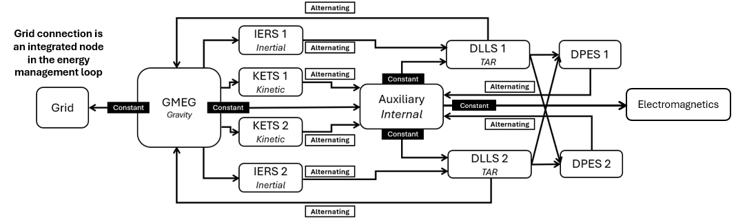
Instead of letting waste energy escape as heat, friction, or structural shock, GMEG-Zero channels forces through a closed internal network:
- Gravity Drive (APFE®):
Continuous downward force harvested along the ±30° sloped rounded rectangular track feeds straight into primary drive shaft torque. - Speed Regulation (KETS):
Excess kinetic energy during operation runs is harvested automatically to maintain complete speed stability. - Track Reset Power & Energy Scavenging (DLLS & DPES):
Mechanical flywheels handle the heavy short-burst torque needed to tilt the track, insulating the motors from shock loads. During each tilt, DPES supercapacitors catch the off-duty motor power, recycling it back into the internal loop to lower overall motor power input. - Shock Absorption & Kick-Start (IERS):
Deceleration shock at the end of a track reset is cushioned by spring banks bringing the track to a soft close, storing elastic energy to kick-start the next reset.
2. Real-Time 60 Hz Control Engine
Our custom Digital Twin software acts as the machine's central control unit:
- High-Frequency Monitoring:
Evaluates 61 live telemetry variables across Spatial, Torque, and Energy Balance dashboards every 16.667ms. - Precision Track Timing:
Dynamically determines track tilt triggers (±30°) to enable continuous operation.