
.jpg)

Gravitational Mechanical Energy Generator
We operate the Patent Pending Gravitational Mechanical Energy Generator, or GMEG for short. This revolutionary generator combines different natural resources for energy generation and continuous motion.
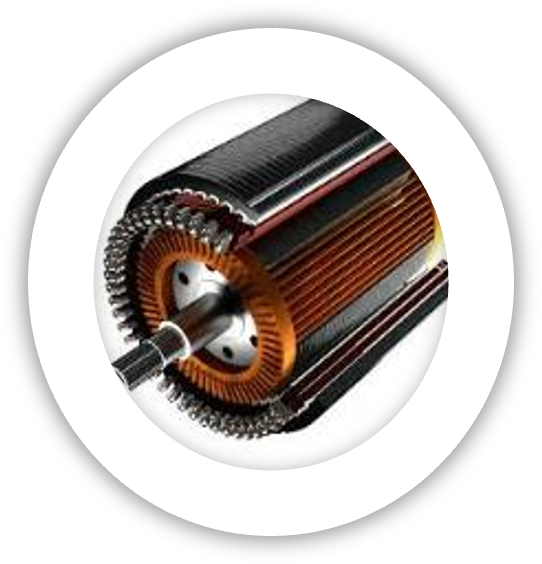
The main generator is powered by the force of gravity, but cannot provide its own continuous movement as the laws of physics prevents that. In order to ensure constant operation, a DC motor is added to the system which can either be main battery or solar powered and provide part rotational movement to the main track at intervals.

Double side track
A rounded rectangular track is provided for the gravity enablers to run in.
It is a double sided track connected with stabilisers to ensure distance symmetry between the two track parts.
Each side hosts an internal sprocket over which a chain runs to ensure it stays centered.

Gravity enablers
In order to provide rotational movement, gravity enablers runs in the track.
The gravity enabler is attached to the chain with a steel rod, which is connected to a wheel on either side
Further supports are provided on each side for lead angling weights to be attached. This keeps the weight bundles in place during operation and is the responsible for converting the gravitationla potential energy into mechanical energy.
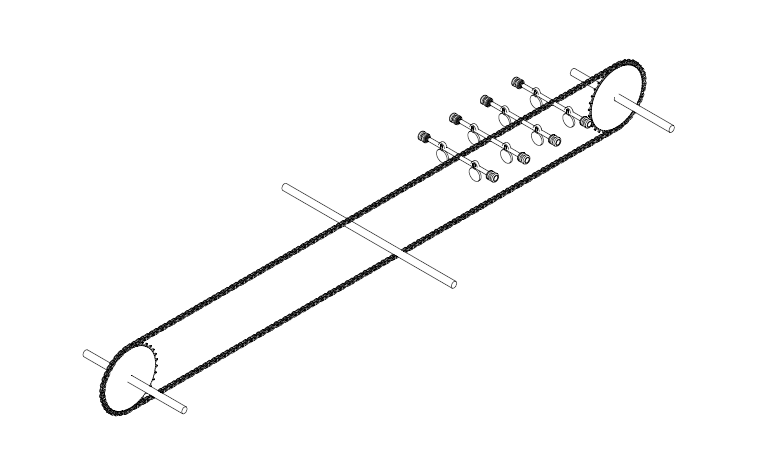
The internal chain
The internal system consists of chain hosted on a 32 tooth sprocket on either side.
1 or more gravity enablers are connected to the chain, and when provided with a downward plane, gravity enacts on the gravity enablers with a downward movement. YThis in turn provides movement to the chain which in turn provides rotational movement to the internal sprockets.

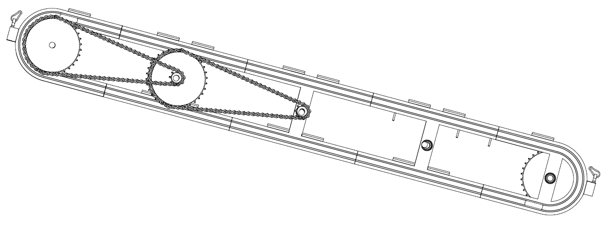
Increased rotational conversion system
The track provides supports with ball bearings for steel rods to fit through. The central steel rod is the main output shaft, and the far left and right steel rods hosts the internal 32 tooth sprockets.
The track can facilitate a increased rotational conversion system for the output shaft. This can be designed with either 1 set or 2 sets of external sprockets connected by chain.
The rotational conversion system is first connected to the either of the far side rods, which connects by chain to the central rod for rotational mechanical energy delivery.
Track part rotational movement
A DC motor is attached to the central rod to provide part rotational motion to the track in either a clockwise or anti-clockwise direction.
This motion is activated when the gravity enablers reaches a specific point at the bottom of the track, which allows the gravity enablers to travel around the rounded corners of the rounded rectangular track and continue the motion on the opposite side of track.
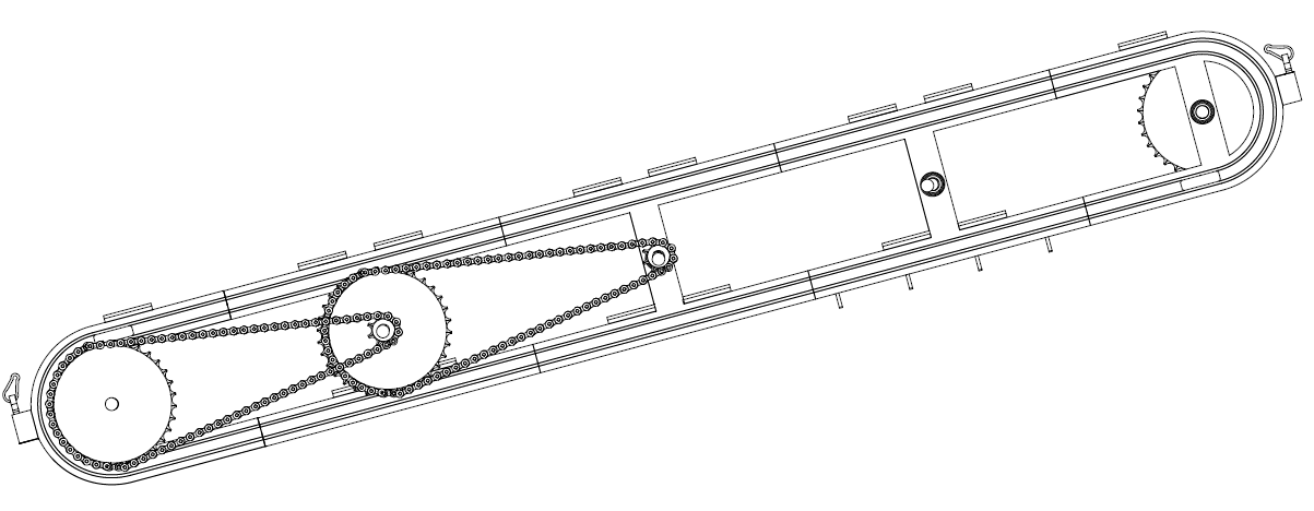
Continuous motion
As demonstrated here, the DC motor alternates the part rotational movement in either a clockwise or anti-clockwise direction to ensure continuous.
Operationally the DC motor will be in standby mode for 3 seconds, and deliver full power for a period of 1 second.